RS232 9 Pin Pinout: Here’s What You Need to Know
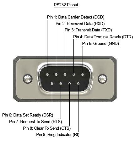
The standard RS-232 DB9 connector uses 9 pins for serial communication between DTE and DCE devices. The pinout above shows each pin and its function — full descriptions below.
What Is an RS232 9 Pin Pinout?
RS-232 monitoring hardware establishes a connection between data terminal equipment (DTE) and data communication equipment (DCE). If you need to monitor or capture data on an RS-232 connection without interrupting it, a passive tap module is the purpose-built solution for that.
RS-232 DB9 Pin Reference
| Pin | Signal Name | Abbr | Direction* | Description |
|---|---|---|---|---|
| 1 | Data Carrier Detect | DCD | Input | Asserted by the DCE (modem) to indicate it has established a carrier signal with a remote device. Used primarily in dial-up modem connections. |
| 2 | Received Data | RXD | Input | Serial data received by the DTE (computer) from the DCE (modem or device). One of the three pins required for basic communication. |
| 3 | Transmit Data | TXD | Output | Serial data transmitted from the DTE (computer) to the DCE (modem or device). One of the three pins required for basic communication. |
| 4 | Data Terminal Ready | DTR | Output | Asserted by the DTE to signal it is powered on and ready to communicate. Often used by modems and serial devices to confirm the host is active. |
| 5 | Signal Ground | GND | Ground | Common ground reference for all signal lines. Required for proper signal interpretation. Not a safety ground — a separate chassis ground should be used where needed. |
| 6 | Data Set Ready | DSR | Input | Asserted by the DCE (modem) to indicate it is powered on and ready to communicate. Paired with DTR to establish a hardware handshake before data transfer begins. |
| 7 | Request To Send | RTS | Output | Asserted by the DTE to request permission to transmit data. Part of the RTS/CTS hardware flow control pair used to prevent buffer overruns at higher baud rates. |
| 8 | Clear To Send | CTS | Input | Asserted by the DCE in response to RTS, granting the DTE permission to transmit. Used together with RTS for hardware flow control in high-speed or industrial applications. |
| 9 | Ring Indicator | RI | Input | Asserted by the DCE (modem) to notify the DTE of an incoming call. Pulses in sync with the ring signal. Rarely used in modern industrial RS-232 applications. |
*Direction is from the perspective of the DTE (Data Terminal Equipment — typically a computer or controller).
Working with these pins to debug a live connection?
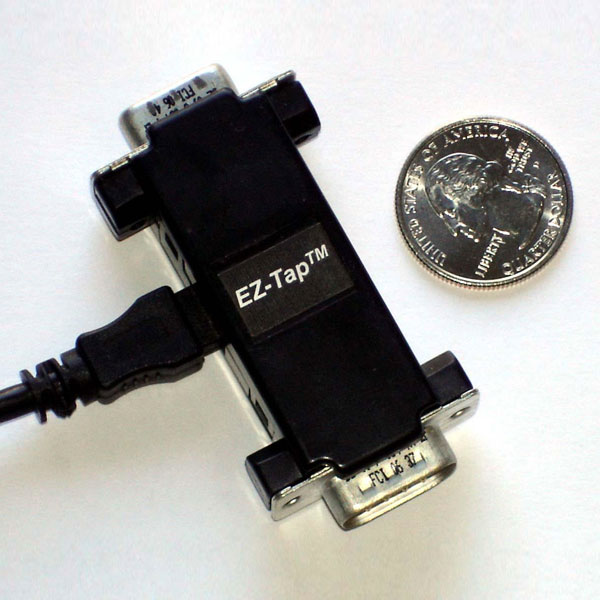
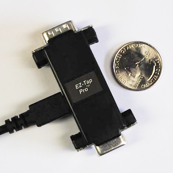
If you need to see what’s actually happening on the wire — both directions, with timing — a passive RS-232 tap sits inline between your DTE and DCE and captures the data without interrupting the link. The EZ-Tap™ is the entry-level option ($265); the EZ-Tap™ Pro adds microsecond handshake-event timing for chasing intermittent faults.
RS-232 Technical Specifications
Electrical Characteristics
| Parameter | Specification |
|---|---|
| Logic 1 (MARK) voltage | −3V to −15V |
| Logic 0 (SPACE) voltage | +3V to +15V |
| Transition region (undefined) | −3V to +3V |
| Maximum open-circuit voltage | ±25V |
| Signal type | Single-ended (unbalanced) |
Cable & Distance
| Parameter | Specification |
|---|---|
| Maximum cable length | ~15 meters (50 feet) at low baud rates |
| Maximum cable capacitance | 2,500 pF (the actual limiting factor) |
| Practical length at 9,600 bps | Up to 15m (50 ft) with standard cable |
| Practical length at 115,200 bps | ~1–2m depending on cable quality |
Data Rate
| Parameter | Specification |
|---|---|
| Standard maximum baud rate | 20,000 bps (per original spec) |
| Common baud rates in practice | 1200, 2400, 9600, 19200, 38400, 57600, 115200 bps |
| Maximum achievable (short cable) | Up to 1 Mbps with high-quality drivers and short runs |
DB9 vs DB25 Connector Comparison
| DB9 (DE-9) | DB25 | |
|---|---|---|
| Pins | 9 | 25 |
| Common use | Modern PCs, industrial equipment, instruments | Legacy systems, older modems and terminals |
| RS-232 signals supported | All signals needed for standard serial communication | Full RS-232 spec including secondary channels |
| Size | Compact — more common in space-constrained designs | Larger — rarely spec'd in new designs |
| Status | Current standard | Legacy — still found in older equipment |
Frequently Asked Questions
The RS-232 9-pin pinout refers to the specific signal assignment for each pin on a DB9 connector used in serial communication. Each of the 9 pins carries a distinct signal — including data transmission, handshaking, and ground — that allows two devices to communicate over a serial connection.
The DB9 (9-pin) and DB25 (25-pin) are the two most common RS-232 connector types. DB9 became the standard for most modern applications because it carries all the signals needed for typical serial communication. DB25 is an older, larger format that includes additional pins for secondary channels and is rarely used in modern equipment.
For basic serial communication, only three pins are required: Pin 2 (RXD – Received Data), Pin 3 (TXD – Transmit Data), and Pin 5 (GND – Signal Ground). All other pins support handshaking and flow control, which are optional depending on the application.
DTE (Data Terminal Equipment) refers to the device initiating communication, typically a computer or controller. DCE (Data Communication Equipment) refers to the device facilitating the connection, typically a modem or serial adapter. Pin directions in RS-232 are defined relative to the DTE.
RS-232 remains widely used in industrial automation, medical equipment, barcode scanners, PLCs, and test equipment where reliable, point-to-point serial communication is required. Despite being an older standard, it's valued for its simplicity, noise tolerance, and long-term hardware support.
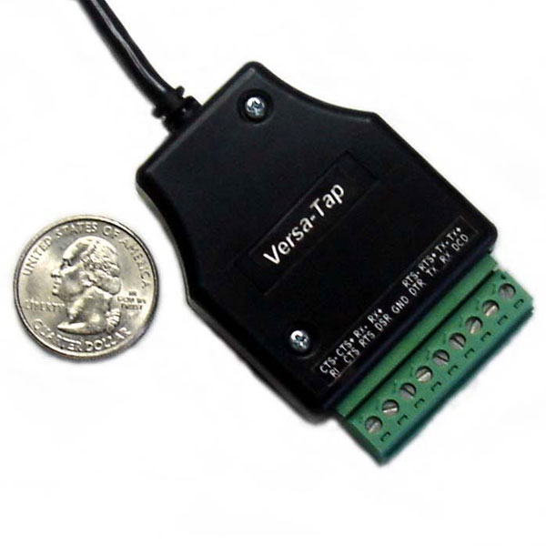
To monitor RS-232 serial data without interrupting the connection, a passive tap device — such as the EZ-Tap or EZ-Tap Pro from Stratus Engineering — can be inserted inline between the DTE and DCE. This allows real-time data capture for debugging, logging, or protocol analysis.