
RS-232 to RS-422/485 Conversion Without External Electronics or Power
RS-232 and RS-422/RS-485 are different electrical standards. RS-232 is single-ended — each signal is measured against a common ground — while RS-422 and RS-485 are differential, carrying each signal as the voltage difference between two wires. Because of that difference, connecting the two normally means buying an external converter with its own power supply.
In many cases, you don't need one. With the right wiring, an RS-232 device and an RS-422/RS-485 device can communicate directly, with no adapter and no external power. It works because the voltage levels each standard produces happen to land inside what the other standard's receiver will accept. Here's how to wire it, why it works, and where it breaks down.
The direct connection
The interface below connects an RS-232 port to an RS-422/RS-485 port using only the existing signal lines and a shared ground — no converter chip and no power brick.
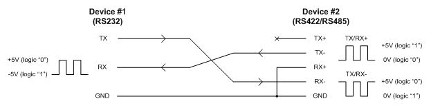
If you need a refresher on which RS-232 pin carries which signal, see our RS-232 9-pin pinout guide.
Why does this work?
The wiring satisfies the voltage-level requirements of both the RS-232 and the RS-422/RS-485 receivers at the same time:
- When the RS-232 device transmits logic 1, its driver applies a -5 V signal to the TX line, which the RS-422/RS-485 receiver sees as a differential +5 V (0 V on the paired line minus the -5 V on TX), or logic 1.
- When the RS-232 device transmits logic 0, its driver applies a +5 V signal to the TX line, which the RS-422/RS-485 receiver sees as a differential -5 V, or logic 0.
- When the RS-422/RS-485 device transmits logic 1, its driver applies 0 V to the TX+ line, which the RS-232 receiver sees as 0 V, or logic 1. RS-232 receivers expect a negative voltage for logic 1, but their actual switching threshold is around +1.5 V rather than 0 V — so they interpret a 0 V input as logic 1.
- When the RS-422/RS-485 device transmits logic 0, its driver applies +5 V to the TX- line, which the RS-232 receiver sees as +5 V, or logic 0.
Limitations
This approach is elegant, but it's not a universal replacement for a real converter. Two things to keep in mind:
- Cable length and baud rate stay at RS-232 limits. If you're converting specifically to get the longer cable runs RS-422/485 allow, this won't deliver that — you're still bound by RS-232's distance and speed.
- You need a solid ground between the two devices. The conversion depends on a shared ground reference. Without a good ground connection, the receivers can't reliably interpret the signal voltages.
When to use this approach — and when not to
The direct connection makes sense when:
- The run is short and the baud rate is within normal RS-232 range.
- You want to avoid the cost, power, and bulk of an external adapter.
- You're bench-testing or prototyping and want the simplest possible setup.
Reach for a proper powered converter when:
- You need RS-422/485's long-distance capability or noise immunity over a long run.
- You're driving a multi-drop RS-485 bus with several nodes.
- The application is permanent or safety-critical and you want full standard compliance.
RS-422 vs. RS-485
RS-422 is typically point-to-point (one driver, one or more receivers), while RS-485 supports multi-point buses where several devices share the same pair of wires and take turns driving the line. The direct-connection trick above behaves the same electrically for both, but if you're wiring a multi-drop network, the topology matters — see our guide to RS-422/RS-485 wiring topologies.
Frequently asked questions
Can you connect RS-232 directly to RS-485 without a converter?
In many short-run, standard-baud-rate cases, yes. The wiring shown above lets an RS-232 device and an RS-485 device exchange data directly, because each standard's output voltages fall within the other's acceptable input range. It does not extend cable length beyond RS-232 limits.
Do you need a power supply for the conversion?
No. The direct connection uses only the existing signal lines and a shared ground. There's no converter chip to power, which is the main advantage of this method.
Will this work over a long cable run?
No. Cable length and baud rate remain capped at what a standard RS-232 channel supports. If your goal is to use RS-422/485 specifically to drive a longer cable, you'll need a powered converter instead.
Monitoring an RS-422/RS-485 link
Once your link is running, you'll often need to see what's actually on the wire — especially when a conversion isn't behaving. The Versa-Tap passive tap module monitors RS-232, RS-422, and RS-485 on a single device, capturing both sides of the conversation with the timing data you need to track down where a connection is going wrong.
Questions on a specific setup? Email us or call (858) 663-1841.